The hardware can be divided into the interior electronics, and the enclosure. The important bit would seem to be the former, but I'll cover what I used for the latter for the sake of completion.
Interior Electronics
The main brain of the DivingBoard is a Raspberry Pi. I used a Pi 3B+, but others should work just fine. I'd recommend keeping costs down by going for an older Pi- anything beyond a 3 is frankly overqualified for the task, and will waste money and power. A Pi Zero 2 might work quite well, but I've not had the opportunity to test with one yet.
The potentiometers used are 10K linear, and the encoders are the five-pin type, with three dedicated to the knob and two to a separate momentary switch. The LCD is a 4x20 HD44780 Character LCD. All can be found on Rapid Electronics, Mouser, Adafruit, etc.
The Pi can't handle analogue inputs for pots, nor low-latency inputs for the encoders, so an Arduino Nano (or similar) is used to read from them, and then report it's findings back to the Pi via serial over USB. Buying Arduino boards directly from the Arduino Foundation supports them, but buying cheap clones is much more economical. A Nano is ideal for this project due to it's small size, but any will do.
Exterior
A tupperware container with a bunch of holes drilled and cut into it. This was done for two reasons: firstly, the plastic is durable and easy to work with. Secondly, the removable lid means that I can easily remove the front panel to access the interior electronics, if the need arises. If I had more foresight, I could have sprayed the inside surface of the tupperware silver, black or some other swish-looking colour to improve the general appearance, but that's a fairly small detail.
The nice thing about making your own gear is that you can decide what it looks like. So long as the basic layout is the same, the case could easily be made from some lovely hardwood, or perhaps (as in my original prototype) half a cardboard box- whatever you prefer.
Assembly Instructions
With accompanying pictures from the assembly of the second prototype (as featured in the demo video), as the first one really was just crappy cardboard which was more a liability than a protective shell. I'll try to break everything down properly- email me via the contact details on my main page if any clarification is necessary.
Enclosure and Electronics
Once you've got all your components, test out the layout in advance of starting out by 'mounting' all of the components onto cardboard. Give each knob a few centimeters of clearance so that you can easily adjust one without jogging the others. This will make positioning the components for the final version much simpler.
Then:
Grab a tupperware box- something roughly 300x150mm should be big enough. Try to find a decently sturdy one with a flat lid (for easier component mounting) and latches, as these are more secure than the press-fit variety of lid.
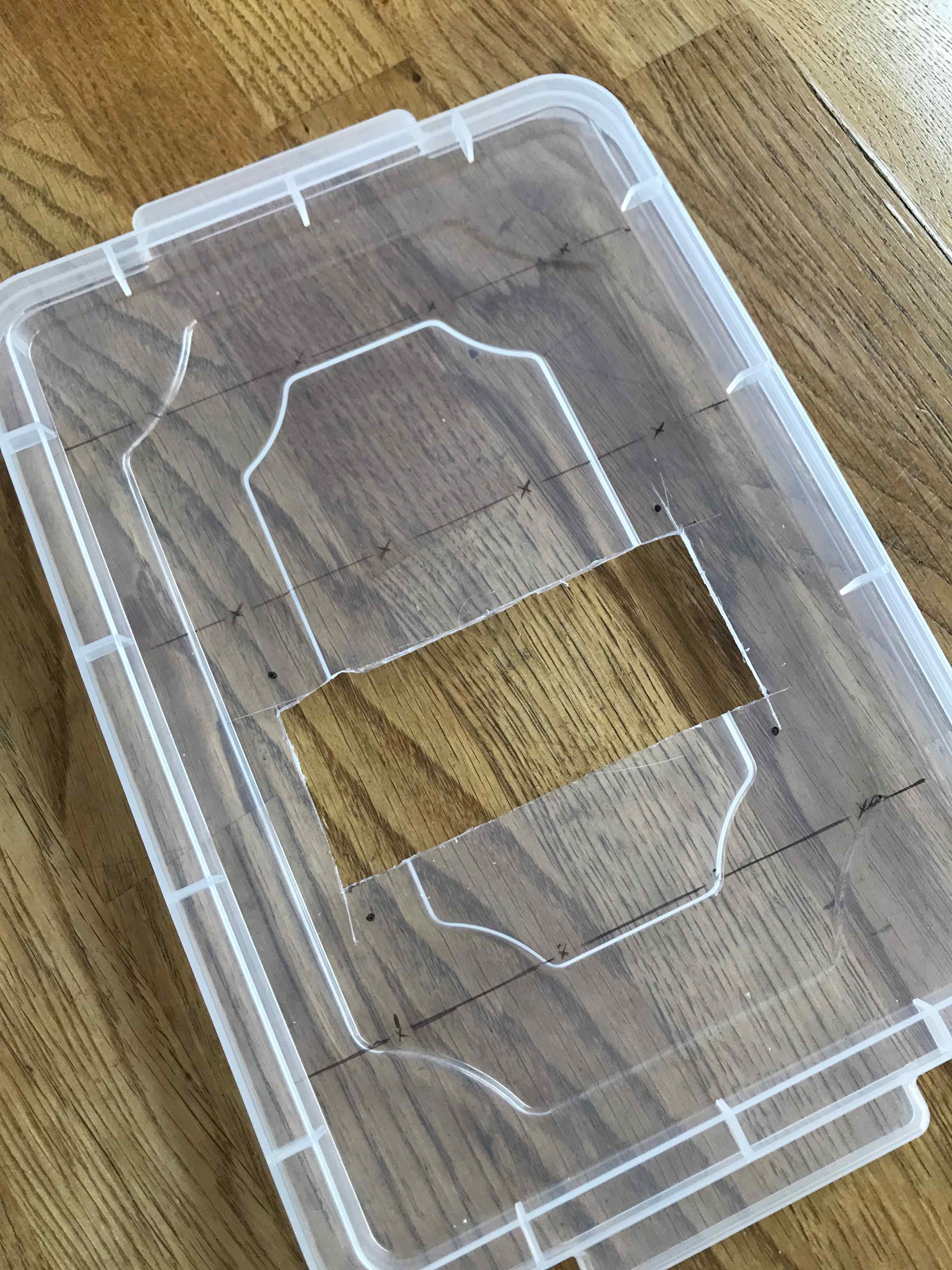
Use a pocket knife or something similar to cut holes in the main box part of the tupperware for cables- one USB MIDI cable, and one micro USB power cable. It can be nice to cover up the sharp edges created with electrical tape or something similar.
Picture
Cut a hole about 5/8 of the way down the lid for the LCD. Get dimensions for this hole from the component datasheet you're working from.
Drill out holes for the potentiometers and encoders. Again, get dimensions from the datasheets, and follow your cardboard alignment guide for best results.
Some potentiometers will have a little peg sticking out of the front face, meant to prevent rotation of the component once installed (see image). Take note of these if you have them, and drill out holes for them- they're super useful.
Many components will have a washer and nut to fasten them in place when mounting them like this. For those that don't (such as my encoders and LCD), hot glue and a bit of improvisation do a good job. My LCD is held in place by four split pins, going through four specially-drilled holes in the lid, and then through the mounting holes in the LCD board- does the job pretty well.
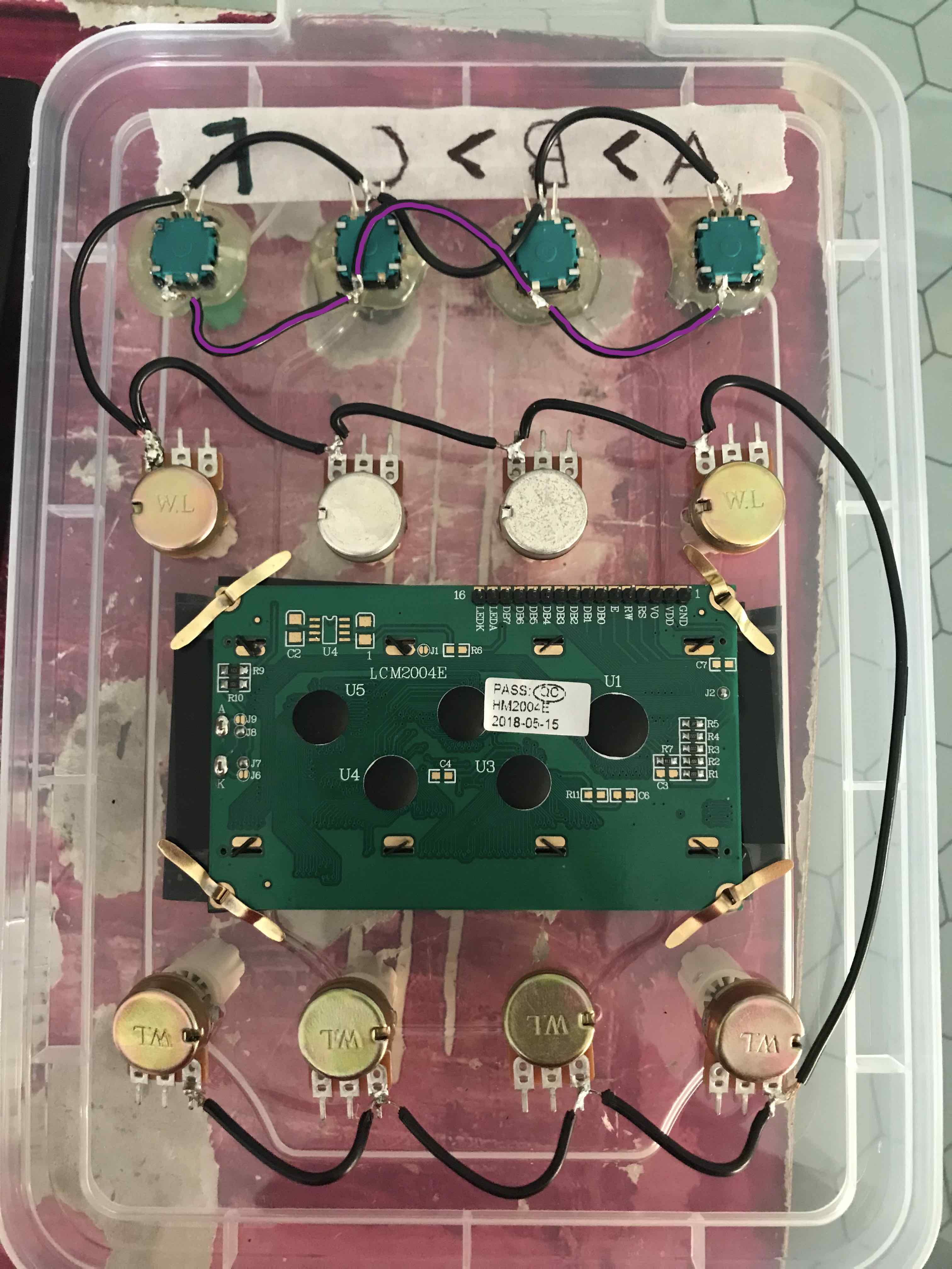
Now, we solder. First up are the negative/ground and positive/5V power lines. For the potentiometers, the negative pin is usually the one on the right, as viewed from behind. For the encoders, check the datasheet.
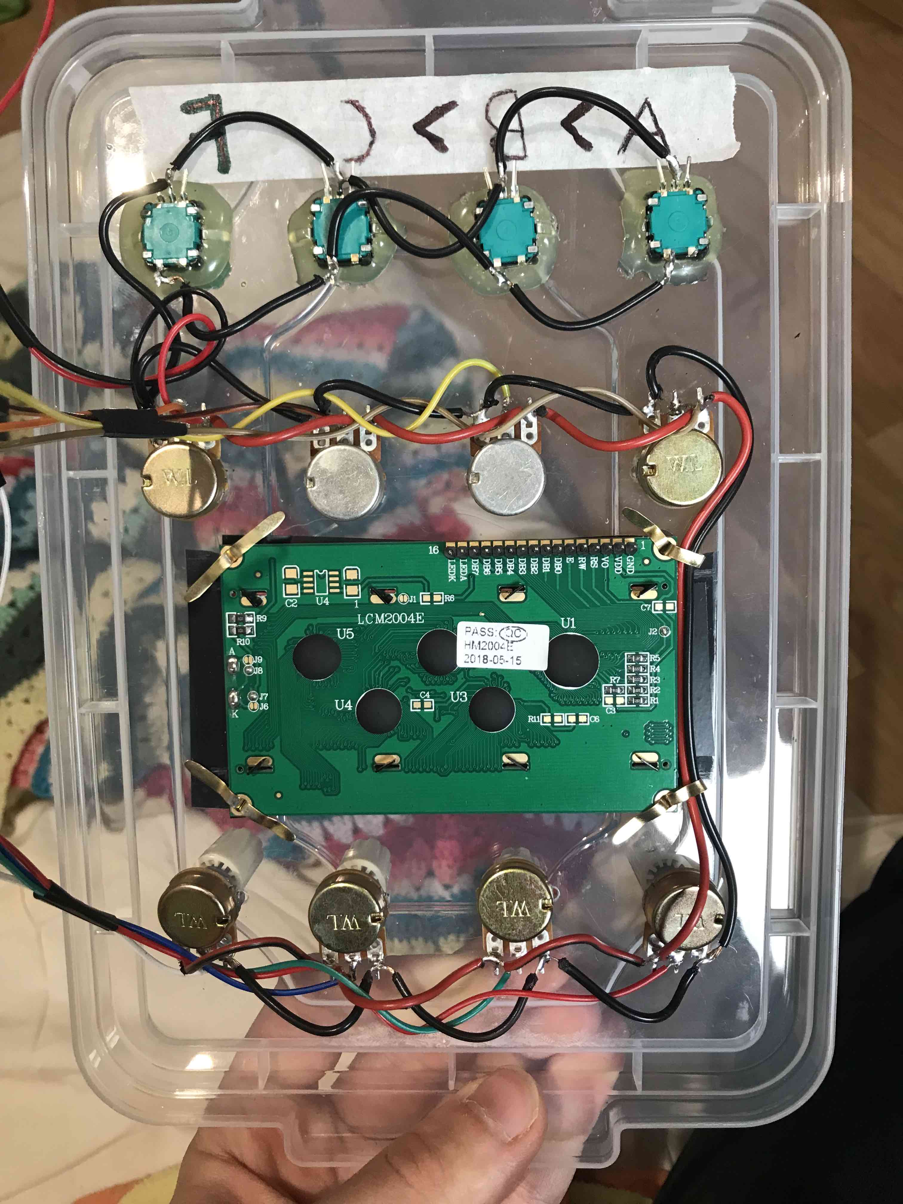
As the encoders and potentiometers are all being read by the Arduino, they should all have a common ground. The exception to this is the momentary switches on the encoders, which are to be read by the Raspberry Pi. As such, they should have a separate ground wire (marked here in purple).
I am not very good at soldering, so the following pictures may cause distress amongst those with skills.
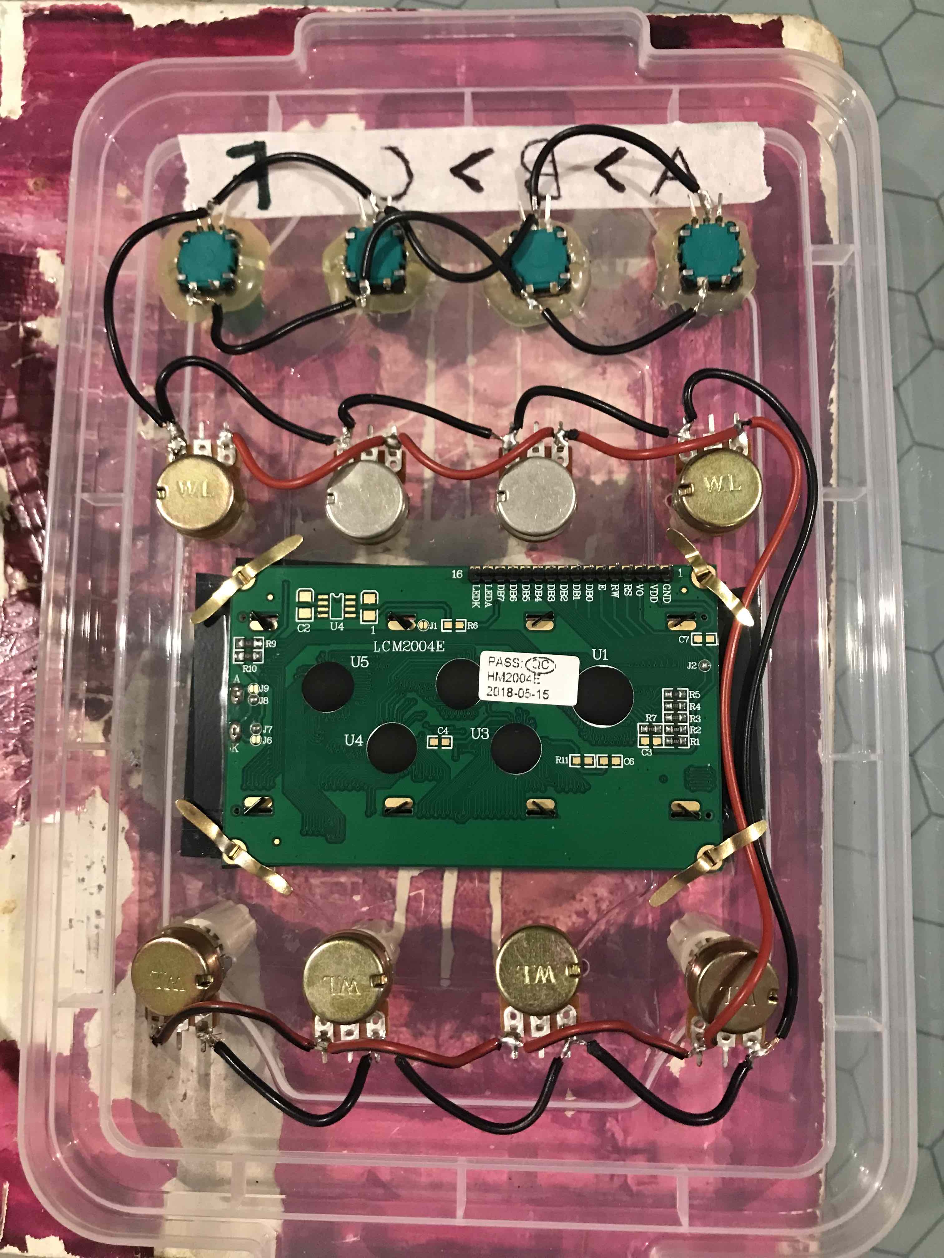
Same again, but for the positive potentiometer pins- usually the one on the left, as viewed from behind.
If you are in need of wire for this sort of thing and snipping the ends off of a load of jumper cables seems wasteful to you too, speaker wire seems to do a good job. I got a bunch of cheap stuff from my local hardware store. Pre colour-coded too, which is nice.
Next up are the data lines for the pots and encoders. For the pots, the middle pin is the data readout, and these connect to analogue pins on the Arduino. Colour-coding really helps here.
As my model here is a prototype, I soldered on jumper cables with one end cut off, for ease of breadboarding. For a permanent installation, you may as well solder wire directly to both the pot and the Arduino.
Each encoder has two data pins, which each connect to a digital pin on the Arduino. Make sure to get these the right way around, or they'll scroll the opposite way than you expect. Consult the datasheet and the Encoder.h library documentation for guidance.
Consistency is key- so long as all the encoders are soldered in the same way, you can at the very worst just edit the Arduino programme to send 'negative' instead of 'positive' and vice-versa for encoders, which should straighten everything out.
For the LCD and encoder buttons, you can solder or use jumper cables and a breadboard, depending on how permanent you feel this project will end up being. My decision to use jumper cables and a breadboard was driven by this project being a prototype, and the Pi involved being my only one. If I were to re-make this now using a Pi Zero 2 or something like that, I'd solder everything to ensure solid connections.
Picture
It's important to make sure that the connections made in the hardware match up with the software. It doesn't generally matter which analogue pin each potentiometer is connected to, but if they don't match up with what I've written in the software, then the alignment of control labels on the LCD will be completely different to the physical locations of those controls. To aid in the confusing task of wiring everything up, here are snippets from my working documents and the DivingBoard code, which should help to get everything sorted:
Encoder buttons (where the number at the end of each line matches up with a pin on the Raspberry Pi, according to the RasPi pinout):
LCD:
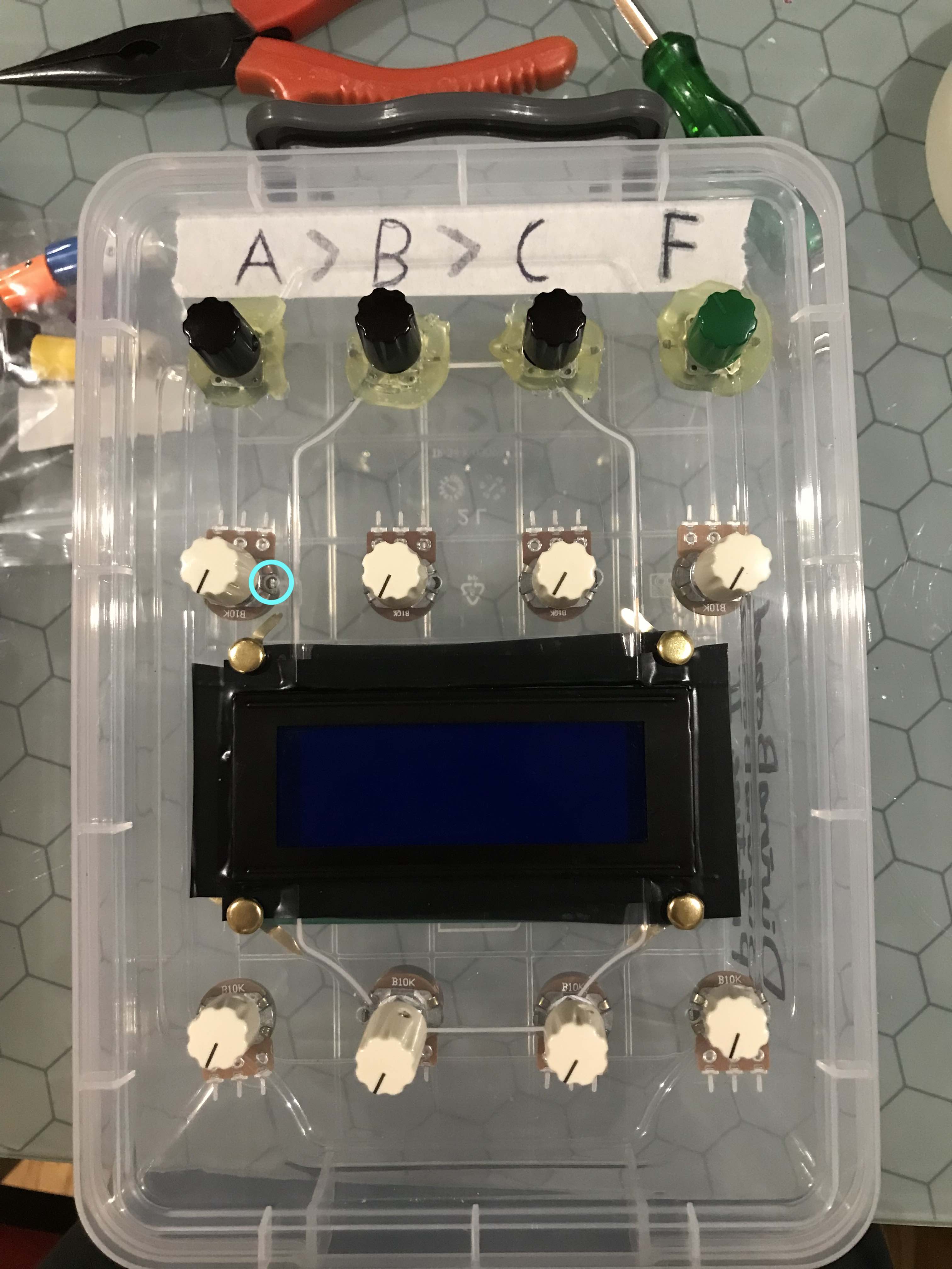
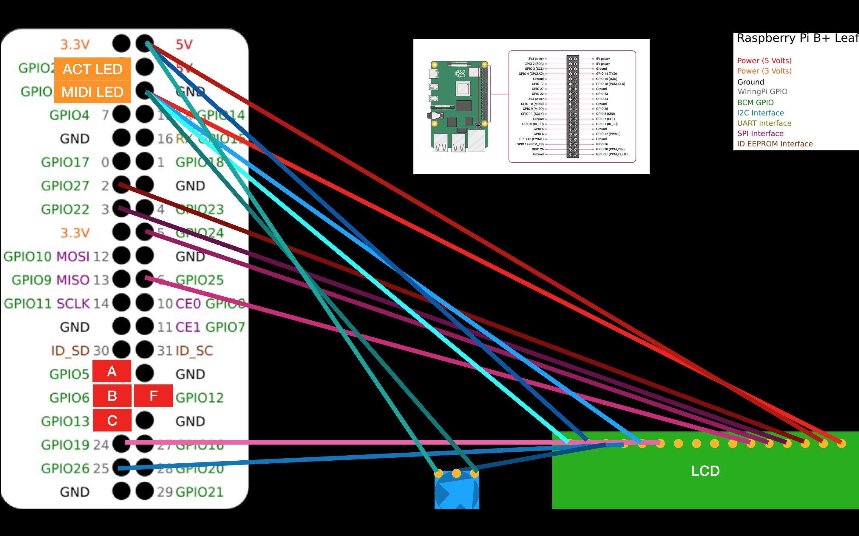
This bit's really rubbish to look at. Below is the diagram I made to help myself remember the wiring for the LCD, and below that is the code block that acquaints the Pi and the LCD:
This image also shows the locations of the encoder momentary switches (marked A, B, C and F in red rectangles) and the completely optional LED indicators, which you can wire up if you like. I used an RGB LCD with the channels wired up to 3.3V, GPIO 2 and GPIO 3 respectively. This gives an insight into what the code is doing as you use it, which can be neat to look at.
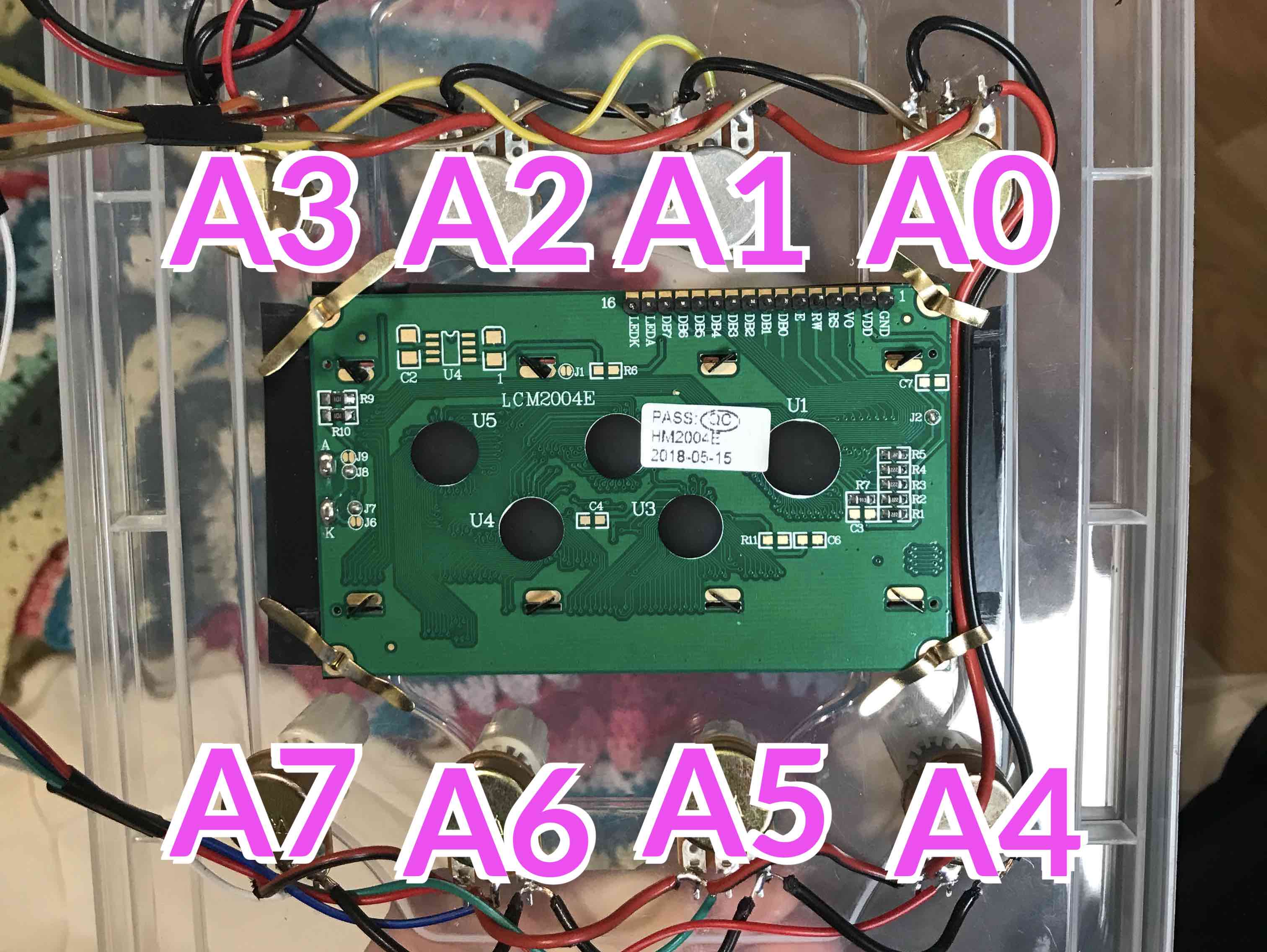
Rotary Potentiometers:
These are wired such that from the front, they match up with the analogue pins in ascending numerical order: A0, A1, ..., A6, A7. An image may be helpful here:
Once all the wiring is done, upload the ControlReporter.ino sketch to your Arduino, and, via the Arduino IDE's Serial Monitor, test that each control shows what you expect when manipulated. The messages you recieve back should be in the form b'',x,y,\\r\\n, where x is the address of the control, and y is the value of that control. If any controls seem to be sending the wrong messages, now is the time for resoldering.
Software
Getting the software up and running is started by uploading the Arduino sketch as described above (if you've not done this before, check out the Arduino primers on their own website, and maybe try a few of the example projects in the Arduino IDE- it's neat stuff). Once this is done and all controls are confirmed to be working, it's Pi time.
The Raspberry Pi is the central computer for the project. It's running headless (ie without a screen) in situ, but you'll need to connect peripherals in order to set it up. Basic steps are as follows (and shoot me an email or check Google if things don't make sense):
Download the Raspberry Pi Imager from the Raspberry Pi Foundation website, and install standard Raspberry Pi OS with the desktop (or go CLI only if you're confident to do so). Skip out on the full version with all apps included- none of them will be used.
The installer will give you some options for installation. Keep the default username- there are some absolute filepaths which depend on this in the current version of the software. Enabling SSH is a good shout, because from there you can set up the VNC connection, which gives you wireless access to the desktop- great for debugging once the Pi is stuck in the tupperware. You'll have to put in Wifi information for a known network if you want to access that though- I'll omit further SSH instruction here because there are good guides out there, and I don't want to muddy the waters.
Once the Pi is alive and well, and however you're connected to it, download the DivingBoard software linked at the bottom of the main page. Unzip it so that the folder 'DivingBoard v...' is on the desktop. From there, there's a README.txt file which contains most of the rest of the setup instructions. You'll need to install some libraries - as before, I shan't try to explain that here when there are better guides elsewhere.
Connect stuff up: the Pi and Arduino via a USB-A port on the Pi, and the encoder buttons and LCD via the GPIO pins. Given the limited space to work with, and if you're using jumper cables and breadboards, this may be finicky.
Once the electronics are connected, and everything in the README is set up and working, connect the JD-Xi via the USB computer connection and turn it on. Go into the system setting on the synth and switch the parameter Tx Edit Data to ON, and Sync Mode to MASTER. Once this is done, then if the synth and Pi are connected and on, and no DivingBoard code is running, the synth shouldn't respond to any user input. This is weird, but likely means it's all working.
Start up the DivingBoard software either by directly launching Launcher.sh, or by running MainMenu.py. Either way, everything should come alive and start working.
The list of saved controls will obviously start out empty, so the DivingBoard won't do much. The best thing to do initially is to navigate to the main menu and then to the adder.py programme to start setting stuff up. From there everything should start to come together.
Assumptions make an ass of (mainly) me. The above instructions are fairly broad strokes covering the assembly process, and I'm sure there's plenty of room for mistakes. If any clarification is needed (and as I've mentioned above), email me with details of the problem and I'll try and sort it out.
A few of the people who've heard about this project online have expressed interest in acquiring a DivingBoard themselves. I can't necessarily promise a full-quality product (there are too many glitches in the software at the moment for me to be completely happy with it), but if anyone was willing to pay the cost, I'd potentially be happy to put one together and send it out. I imagine for parts, labour and shipping it'd come to around £100. If the interest is there, let me know and I'll see what I can do.