An old set of organ pedals, upgraded into a MIDI keyboard by me, for a friend in a prog band.

A friend of mine is the guitarist in a prog band called Zenden Greenpurp, and he had a set of old organ pedals from a home organ. He knew I'd made a few MIDI projects in the past, and asked if I could fit the pedals with a MIDI output for Taurus-adjacent shenanigans. I obliged because I'd been planning on making my own set at some point, and this gave me a reason to actually get going with it.

The back of the instrument, with my incredible branding skills.

The electronics, mounted on a PCB (Puny Cork Board).
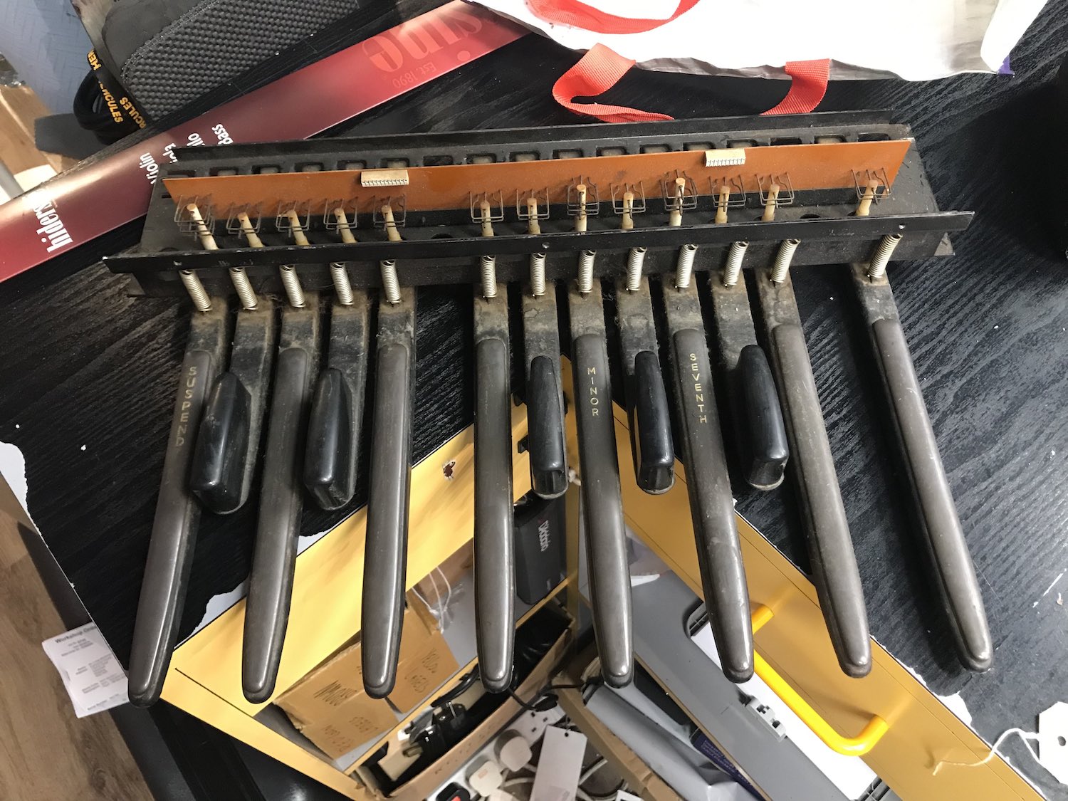
After making arrangements for the pedals to be dropped off at my work, I waited patiently by the counter. I was pulled away by some customers for the best part of an hour, and came back to the counter to find the above pedals in a Tesco bag. A quick test at work revealed that all of the keys were fully mechanically functional, moving up and down with a reliable and robust motion. They were also filthy.
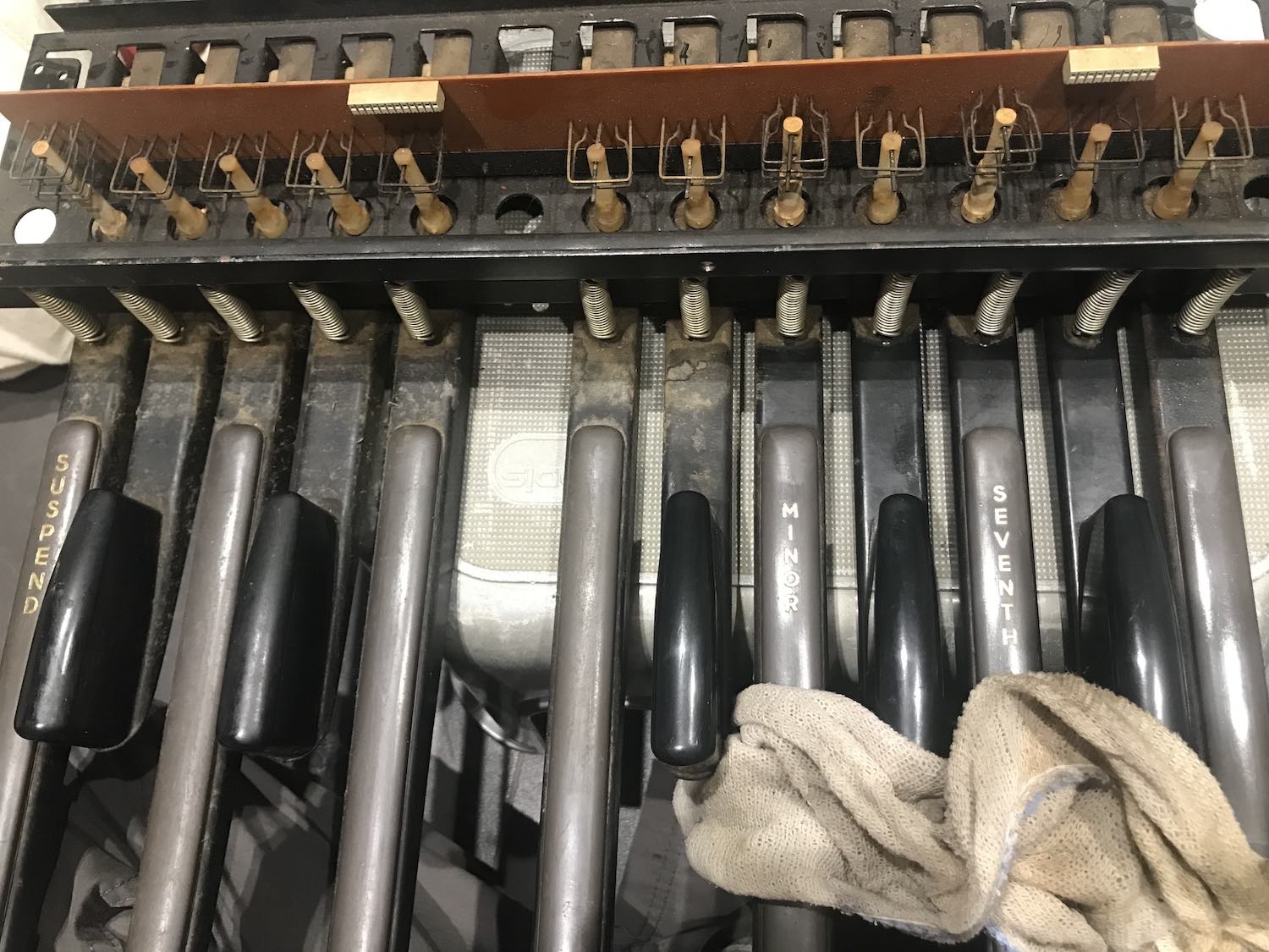
Having brought the pedals home, I set about cleaning them with a cloth soaked in dilute white spirit. This got pretty much all the dirt and other grime off, excluding that which was out of reach. Inspecting the electronics present revealed some rather convenient sockets for jumper cables, and intact (though very dirty and oxidised) contacts for each key. Provided that the sockets and contacts were usable, things looked promising and potentially quite quick and easy.
A microcontroller was the clear choice of brain for this project; quick startup, low power draw, and low latency ruled out using a full computer, for example a Raspberry Pi Zero. Further, as we have a set number of immutable inputs and outputs, there's no potential need to pop the hood, unlike the DivingBoard where re-programming on a whim is one of the main features. I had an Arduino Nano lying around and decided to use that.
The first test programme can be seen above. I hooked up a single key, following the traces on the original PCB to establish the correct sockets to use. I was initially mystified to find that the reading was fluctuating wildly, regardless of which digital input pin I used on the Arduino, or which key I attached it to. This turned out to be fixable by enabling the pullup resistor on the Arduino pin; what this actually does electronically speaking, I still don't know- it sorts the problem out though.
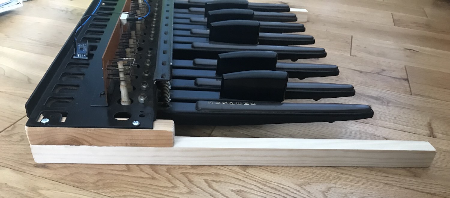
Another problem became evident early on, and is visible in the above video. Without a stand, the pedals have nowhere to travel when you press down on them, rendering them unusable. A quick Wickes trip sorted this problem out, even if the result looks a little rough around the edges. I'm not really going for sleek with this one.
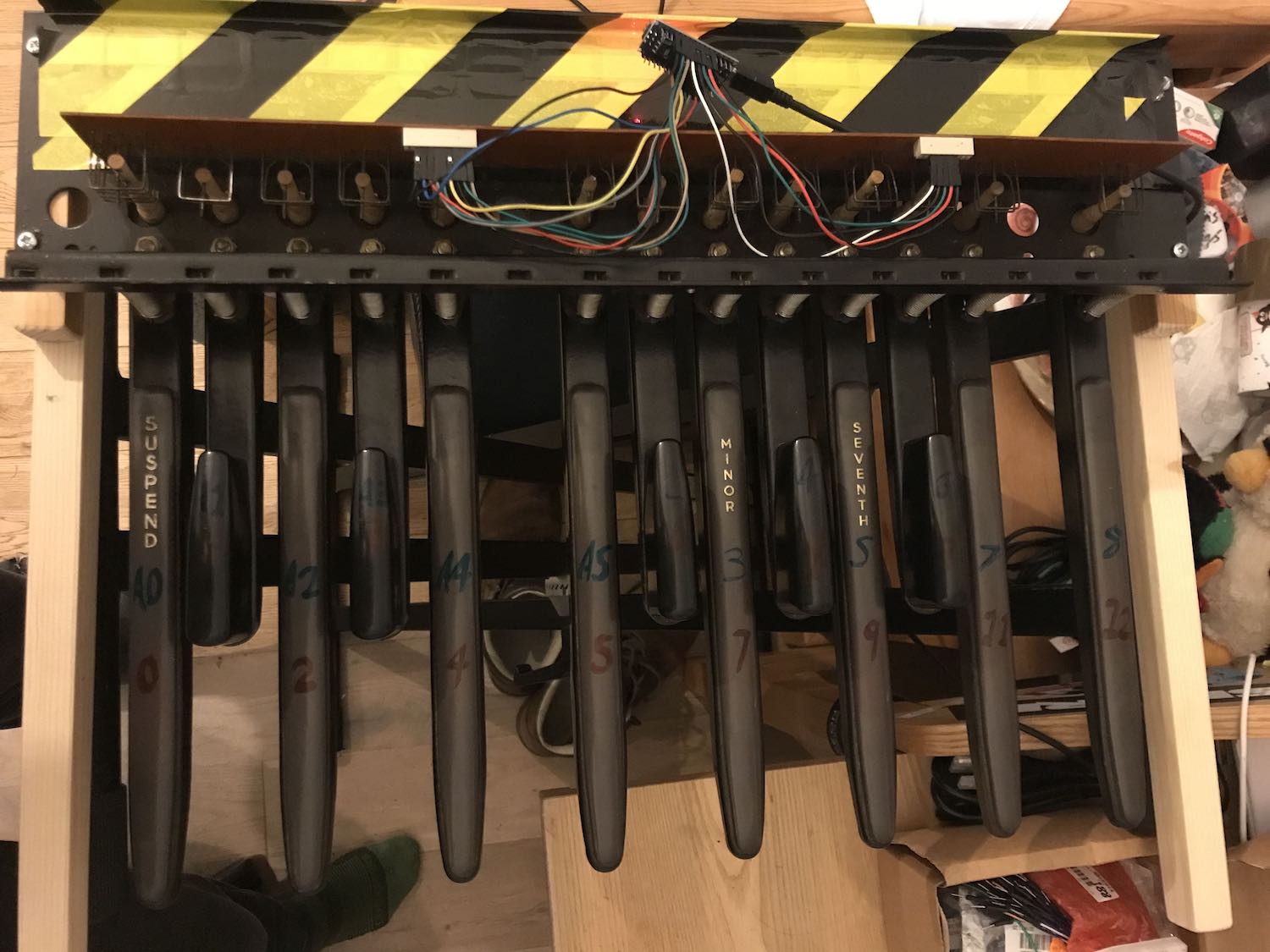
Once I'd tested all of the keys individually to ensure that everything worked, I connected them all up at once. I wrote a programme which checks on them each in turn, storing their current state of 'down' or 'up' as it goes. If the current state differs to the stored state, we know that the pedal's just moved. From this information, the programme can send MIDI messages corresponding to the movement of the pedals.
I found information on outputting MIDI from an Arduino in the official Arduino docs, happily enough. I had some breadboard-friendly MIDI jacks from a previous (as yet unfinished) project, and the provided demonstration from the docs was readily adaptable to my purposes. In not too much time, I had a functional first version. I spent quite a while messing around with this before going any further with the project.
After some discussion with the friend I was making all this for, the full requirements beyond what I'd already achieved were established: octave select, MIDI channel select and latching sustain, along of course with a hard-wearing enclosure.
My initial thought was to use rotary switches for this- the reasons being that I had some, and that they were easy to operate in the darkness of a stage environment with clear 'clicks' to tell you when you'd shifted across by one. Unfortunately I couldn't make it work at the time, as I was very low on Arduino pins. Each separate switch in a rotary selector switch requires a pin on the Arduino to tell you which position it's in, which is more pins than I have to spare. I therefore did away with this idea and instead used rotary linear potentiometers. These gave a continuous reading from 0 to 1023, which I could divide up into even sections to use like a rotary selector, while only requiring a single pin- neat.

I was later made aware by a friend that I could have indeed used rotary switches, and read them using only a single analogue pin by attaching different value resistors to each switch- every position would have a fixed and different resistance value, leading to easy identification of what the user wanted. I would have gone back and implemented this as it's definitely better from a usability standpoint, but by now this project was taking up much of my limited space and my aim was to finish quickly.
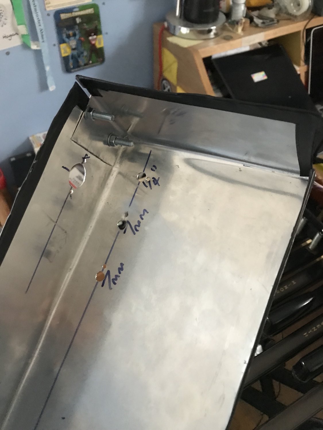
This was made of sheet metal- 0.8mm stainless steel (or possibly aluminium- there was some confusion) to be precise. I shaped this with tin snips, pliers, a hammer and elbow grease, using only eyeballed measurements. The guide line drawn on the sheet metal in the picture above is for the front lip of the lid.
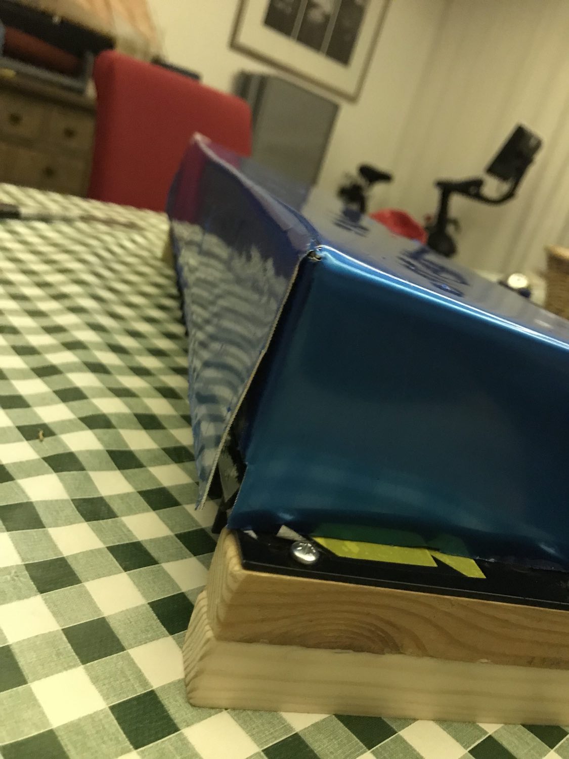
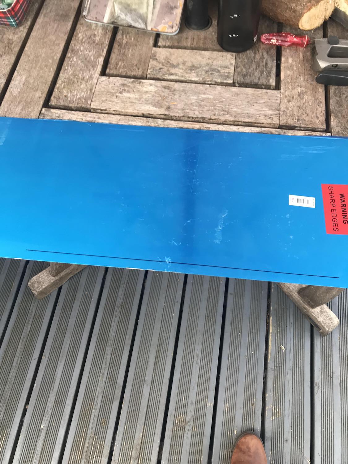
The process of cutting and folding the sheet metal took about half a day, which was much less than I had imagined. It was also rough as hell, but it was good enough for the intended use. The finished shape was bolted together in a few places, and wire tape was placed over all sharp edges as Wickes didn't have much in the way of metal abrasives. This metal lid is held in place at the back by friction, and at the front by three bolts (two push in, the middle one actually screws in). Amazingly this is sufficiently secure for me to lift the whole device up by the lid with no fear of anything falling apart.
The holes were drilled both by me and by a friend who has a bunch of really large drillbits, required for making the holes for the stompbox-style button and the MIDI port. I had to ruin the nice smoothness of the metal a bit in order to de-burr the drilled holes sufficiently for component mounting and safe use, but it still looks mostly fine.
In order for greater stability of the finished product, I replaced my headered Arduino Nano with a headerless Nano Every that I bought; all connections previously made via jumper cables were soldered. I mounted the Nano Every onto a bit of cardboard on a bit of wood to give it some mechanical insulation from the outer surface. My inexperience working with electronics led me to the decision to recreate the breadboard's layout; I made dedicated positive and ground power rails from stripped and solder-saturated wire, and attached all components to these, and then the rails to the Arduino. Not strictly necessary, but it made me more comfortable with the layout as it came together.
I used three LEDs to show the status of various things. The red LED is connected to the Arduino's 5V output pin, and indicates that the board is powered. The yellow LED blinks for every MIDI message sent, to indicate activity. The blue LED indicates whether latching sustain mode is enabled or not. They are all held in place with superglue.
Everything works. It feels reliable to use, and not at all fragile. It's worked with every MIDI device I've tried it with so far, with no glitches. It moves around a little as you play it- I might get some rubber feet to put on it, provided the extra height doesn't mess anything up.
The software can be downloaded here. I plan on making another one of these at some point, for my own use once I've given this one back to it's owner.